Glossary
Definition modules
Blue Planet Orchestration uses definition modules to define data models (for example, Resource Types) or behavior (for example, system Service Templates). The information model is based on the TOSCA OASIS Standard.
Definition modules are stored in the Model Definitions area in the Assets component. Artifact Definitions are the main content of definition modules. The following table lists the types of artifacts.
| Attribute Name | Purpose |
|---|---|
resourceTypes |
Contains Resource Type definitions. |
propertyTypes |
Contains Property Type definitions. |
capabilityTypes |
Contains Capability Type definitions. |
relationshipTypes |
Contains Relationship Type definitions. |
serviceTemplates |
Contains Service Template definitions. |
|
|
Do not attempt to delete built-in artifact definitions, for example, resourceTypes, from the Asset Manager. This action causes instability in the Orchestrate software. |
A definition module can include plans that describe the management aspects of service instances, especially creation and termination. Plans are defined as process models or workflows of one or more steps that manipulate template components or interact with external systems.
Blue Planet treats all definition modules and subsidiary components as source files, managed using an integrated source-code management subsystem based on the open-source Git server. This treatment ensures change control, diff tracking, version control, reverting, and sandboxing.
Definition modules are listed in the Asset Manager and processed by Blue Planet when they are onboarded. RA installation handles processing the definition modules into Asset Manager. RAs appear in Asset Manager after successful installation. You do not need to onboard the RA into Asset Manager.
|
|
From the Blue Planet dashboard, you can access the Asset Manager using Orchestration > Onboarding > Asset Manager. |
Domains
A domain describes a resource or grouping of resources you can configure using a common interface. In some cases, this interface is a CLI interface to a single device. In other cases, it is an API interface to a network management system (NMS) or virtual infrastructure manager (VIM) that pushes configurations to single or multiple resources or devices under their control. The grouping can contain physical and logical resources.
Blue Planet utilizes a resource adapter to communicate to these domains using their specific interface. The RA translates the BP API commands to communicate with the domain and resources controlled within the domain. This means that each domain pairs with an RA. There are several RAs included with the core BP software; other RAs require a separate plug-in you can purchase from Ciena.
Blue Planet possesses multi-domain service orchestration (MDSO) capabilities that allow it to communicate with all the necessary resources, even if in multiple domains, in order to combine the configurations that make up a full, end-to-end service. MDSO uses the concept of domains to connect, discover, and configure all of the resources using their specific interfaces. You can also add a domain to Blue Planet Orchestration by using the appropriate URL and port number necessary to connect to your domain controller.
Navigate to the Domains tab in the UI to add a domain. Fill out the information tabs with URL, port, and user credentials. For step-by-step instructions, see Creating a domain endif::book-build[].
Tenant and sub-tenant creation
Tenants are groups of users that work as part of the same organization. A user is a member of only one tenant. All domains and resources are owned by a tenant.
The relationship between tenants and domains are based on the following:
-
Tenants are a way to group users that are members of a common organization and have the same scope of responsibility in terms of managed resources.
-
Domains are used to own and manage resources. Domains are owned by a tenant.
The Blue Planet User Access Control (UAC) application controls system back-end processes such as multi-tenancy. Users with access privileges can access User Administration using the UI or the REST API.
The Blue Planet Orchestration solution is responsible for associating its resources to respective tenants.
Keep the following rules and guidelines in mind when creating and using tenants and sub-tenants:
-
The master tenant can see all sub-tenant resources.
-
Sub-tenants can see resources within their own tenant and their child tenants only.
-
A user belongs to one and only one tenant.
-
All activities related to user administration of tenants are logged to a persistent database.
Directory structure
Solution Manager manages a directory structure within each application container under /bp2. The bp2 folder maps directly with subdirectory of the BP directory on the host. The bp2 directory on the host is persisted across upgrades and also backed up regularly by the platform.
Name format
In this release, each application directory under Blue Planet (/bp2) now uses the app instance name instead of the fully-qualified solution name. The name of each directory reflects the name of a Docker container. For example, directory /bp2/bpdr.io.blueplanet.orchestrate-16.xx.01_tron_1.2.3/ is now /bp2/tron_1.2.3.
The Docker container name is constructed with /bp2, the application name and the instance index, joined with underscores. A solution name uses the Docker image name (for example, bpdr.io.com/blueplanet/nms:0.1.0), with ‘/’ and ‘:’ substituted with ‘.’ and ‘-)’.
Directory mapping
The Solution Manager creates a /bp2 directory, on both the host and within the Solution Manager container. The bp2 directory contains all the directories for each application instance and uses the name that follows the name format as described in “Name format.”
When Solution Manager runs an application container, it automatically mounts these volumes as read/write:
-
/bp2/{containername}/log:/bp2/log
-
/bp2/{containername}/data:/bp2/data
An application logs in to the /bp2/log directory and stores its persistent data in the /bp2/data directory. The /bp2/config volume is not used at this time.
Blue Planet components/services
This section describes the various components and how they are used within the Blue Planet (BP) solution.
BP solutions
A BP solution is a collection of BP applications linked together. A fig.yml file includes the application definition and how they connected to other apps. This file is derived from the fig project from Docker (http://www.fig.sh/yml.html). The Orchestration solution is one example of a BP solution.
BP applications
A BP application (or app) is an application is a separate package that runs in the BP environment. Applications typically expose a north-bound API to communicate with other BP applications.
A BP application is a Docker container stored in the Docker registry (bpdr). Solution Manager is an example of a BP application.
Some BP applications implement specific functionality that allows the application to be easily reused by other applications. For example, some BP applications are wrappers for a database or a messaging queue.
Solution Manager
Solution Manager is a BP application that manages the BP solutions within the BP environment. Solution Manager is the only BP application that must be installed to bootstrap the system. Solution Manager then deploys solutions based on the solution images that you add to it.
Peer-to-peer versus leader/standby server redundancy
This topic describes two methods of server redundancy, peer-to-peer and leader/standby.
-
Peer-to-peer server redundancy requires a minimum number of members (or instances) that must be present to make the redundancy valid. This method is also called quorum-based redundancy. For Blue Planet, a minimum of three hosts are required for a minimal HA site. +_ Apps with a peer-to-peer redundancy are able to sustain a single point of failure with at least three instances distributed across hosts. Any stateful apps (apps with databases) typically require peer-to-peer redundancy.
-
Leader/standby server redundancy only requires two members or instances distributed across hosts to be able to sustain a single point failure. This method is also called duplex-based redundancy. Currently there are no Orchestrator apps with leader/standby redundancy.
In case of failure, downtime, or excessive traffic at the primary server, you can implement a leader/standby-based redundant server to take the place of the primary server or share its traffic load.
Blue Planet NFVO
With NFV, you can reduce your dependence on single-purpose appliances by taking functions previously built into hardware and implementing them in software that runs on servers, network, and storage platforms. This allows you to serve multiple clients, customers, or tenants with provisional or scalable services.
Standards bodies, such as the ETSI ISG (European Telecommunications Standards Institute Industry Specification Group), developed the NFV architectural framework in 2012. This group continues to work to define a common framework to onboard, deploy, and manage the lifecycle of VNFs.
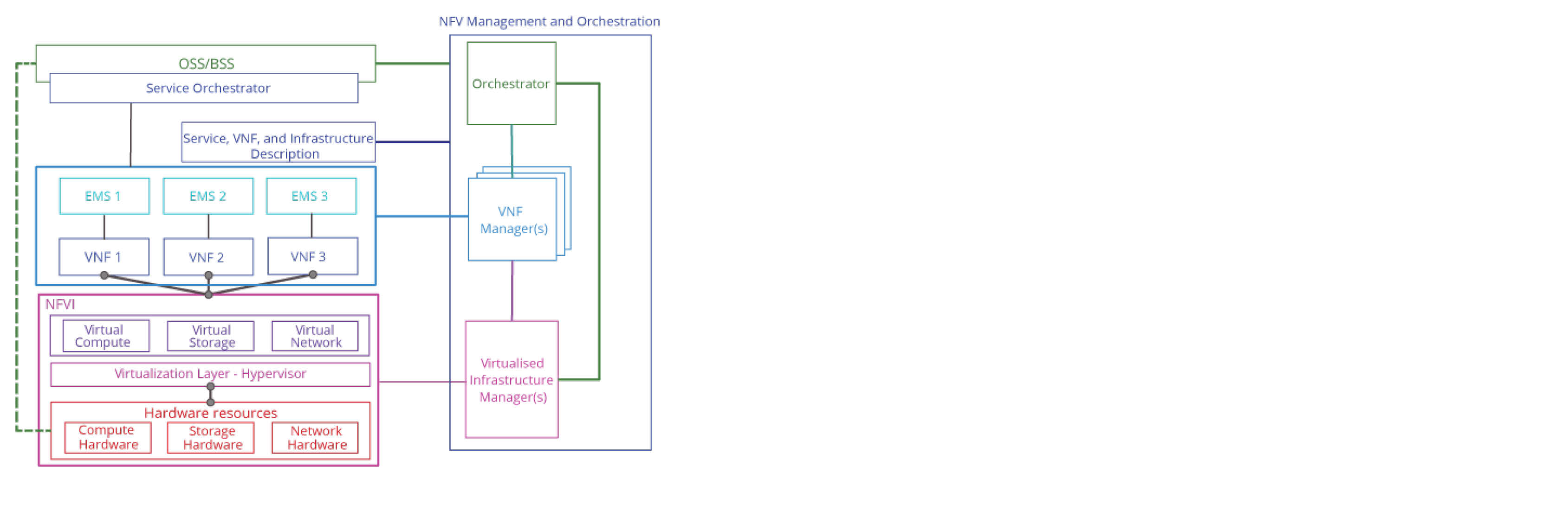
As defined by ETSI, the NFV architectural framework has three functional domains:
-
Virtualized Network Functions (VNF) — A reusable, reproducible, and easily deployable software implementation of a network function. The ETSI NFV management and orchestration (MANO) specifications capture the architecture and reference points. NFV MANO is a working group (WG) of the ETSI ISG NFV.
-
NFV infrastructure — Includes all hardware and software resources that comprise the NFV environment in which VNFs are deployed, managed, and executed. The NFVI can be centralized in one data center or distributed across several sites, and can include customer premise equipment (CPE).
NFVI includes physical resources and the virtualization layer that provides access to virtualized resources through flexible infrastructures that make multiple hardware resources appear as a single entity to the VNF.
-
NFV Management and orchestration (MANO) — Orchestrates and manages the resources that virtualize the NFVI and manage the VNF life cycle.
The figure below illustrates the NFV architectural framework.
Ciena’s NFV TOSCA model reference code uses the ETSI NFV specifications as a base and includes TOSCA definitions for virtual and physical network functions (VNF and PNF), network service, virtual link, connection point, and forwarding path.